Compressed Air System Flow Diagram Technical Materials : Com
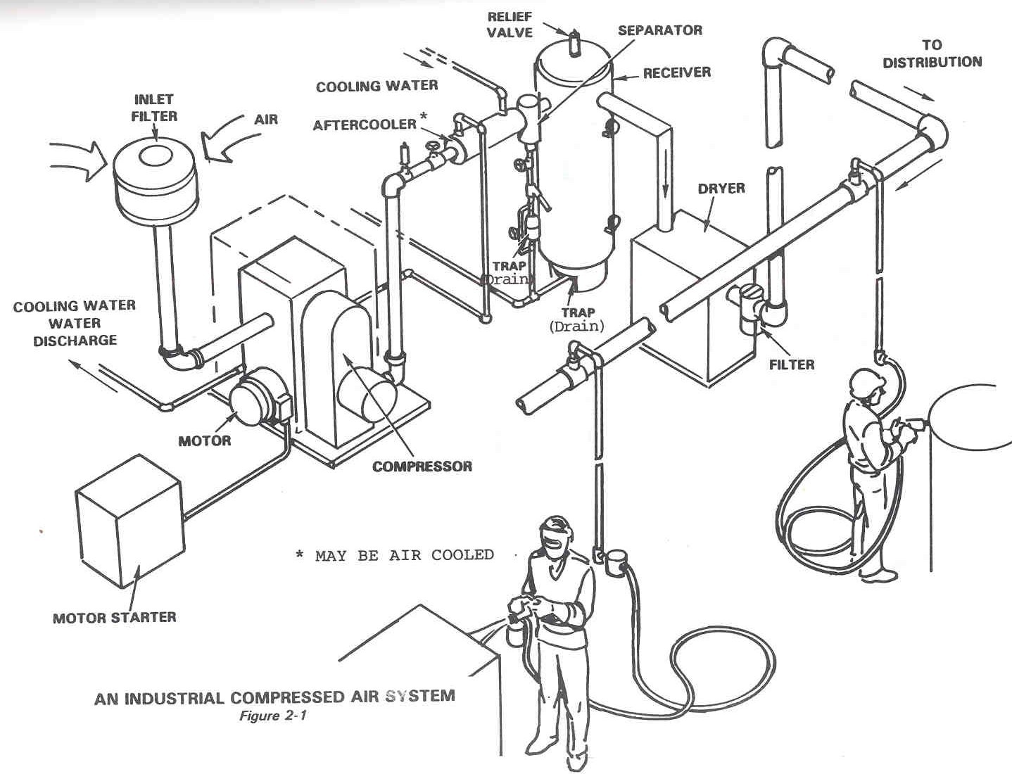
Complete compressed air installations Dfe: lesson 30. compressed air, water and steam Diagram of compressed air systems. 1: compressor; 2: air receiver tank
Screw Compressor Flow Diagram
Compressed air systems by varun pratap singh Compressed air system optimisation Image result for air compressor system layout
Air compressed system storage control evaluation diagram technologies foster provided modified henry cea efficiency reference energy inc john guide
Air compressor in melbourne: how to reduce the costs of your atlasCompressed air system pressure flow Screw compressor flow diagramControl storage and compressed air system evaluations sydney..
38 compressed air system piping diagramCompressed air components systems system technical materials main Compressed air system|| compressed air flow diagram|| compressed airCompressed air piping changes help dairy producer optimize.

Compressed air piping (considerations before buying) i rasmech
Pneumatic control system symbol valve typical pressure circuits device basic air circuit explained basics automation misumi fig under usa costCompressed airpro installations technix Technical materials : compressors and compressed air systemsDesigning compressed air systems.
Piping compressors considerations gardner11 energy-efficiency improvement opportunities in compressed air Compressed air diagramCompressed air system energy dryer schematic drawing refrigerated piping systems industrial pipe filter storage familiar aspects reduction implementing strategies before.

Business energy advisor
Air compressed receivers compressor system secondary consumption assembly systems capacity cooler after time over points beforeAir compressed flow system pressure correct valve deviations releases control storage figure What is schematic drawingsCompressed air systems (energy engineering).
Standards for instrument air systemSchematic diagram of the compressed air system Low cost automation tutorialCompressor pressure.

Atlas copco air compressor melbourne compressed systems pipe schematic filtration
What makes a compressed air system “complete”?A simplified visual guide to compressed air systems Compressed air compressor diagram plant systems energy efficiency compressors system engineering electrical opportunities improvementCummins system air 4bt flow diagrams compressed troubleshooting engines diesel.
Compressed air system schematic systems engineering energy figCompressed air system Compressed air piping changes help dairy producer optimizeCummins 4bt.

Compressed air diagram schematic unit food compressor system water producing figure steam components dairy maintenance engineering
Compressor compressed systems pipeline leakage pointsCompressor dryer piping sharpe cfm refrigerated compressors Energy – compressedairducationCompressed air system installation guide.
38 compressed air system piping diagramCompressed pratap varun Air compressor diagram designCompressed air receivers.
Compressed air systems
.
.


Compressed air system|| Compressed air flow diagram|| Compressed Air

Screw Compressor Flow Diagram
Technical Materials : COMPRESSORS AND COMPRESSED AIR SYSTEMS - Post 1
Compressed Air System

Energy – Compressedairducation

Compressed Air Systems (Energy Engineering)